Building the perfect keyboard: Dactyl build log
Published on Dec 31, 2024 by Impaktor.
Table of Contents
1. Introduction
Somewhere in 2015 I got RSI from +10 h / day of Emacs keybindings (also in my browser conkeror). When you’re in pain, preventing you from working, you’ll play anything, and I found the solution that worked for me was the same as for many others: switching to Kinesis Advantage. And what a lovley keyboard it is. The sculpted key-wells made it such that for the first time in my life I can type without looking at the keyboard - and this is coming from someone who had electric typewriting class in school where we were typed with plastic shields preventing us from seeing the keys.
Around 2018 I started pursuing the possibility to 3D print a second Kinesis-like keyboard, one for the office, one for the home. I found Matthew Adereth’s fantastic dactyl - a parameterized 3D model of a split Kinesis keyboard, with open source / free firmware QMK offering tremendous flexibility and power.
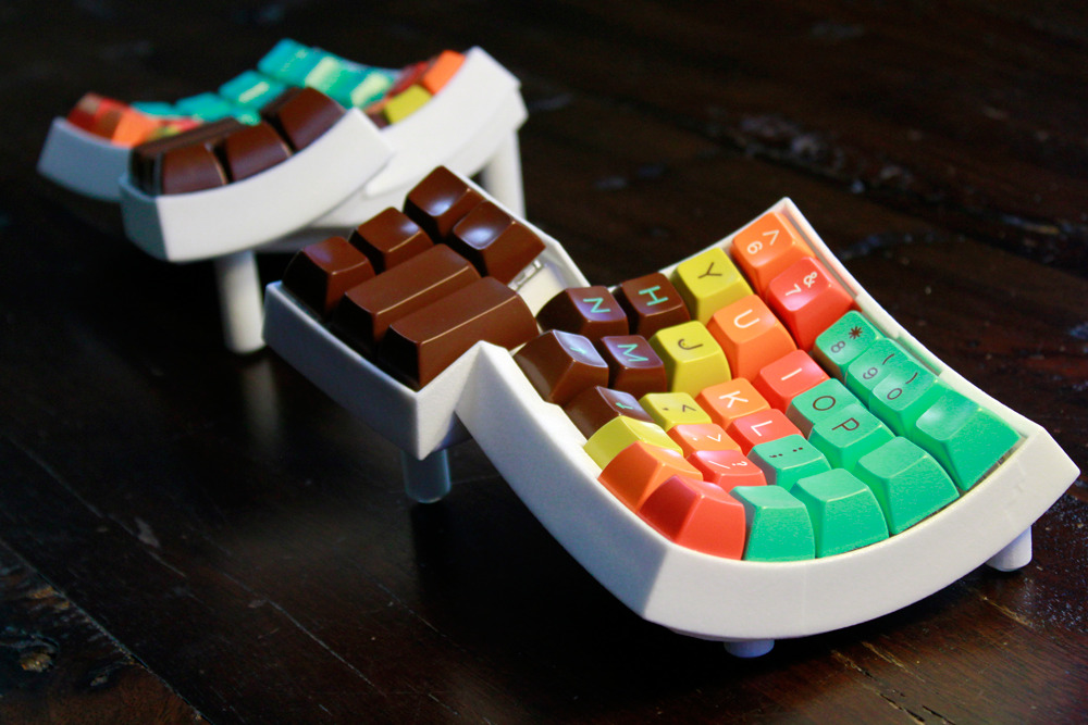
Figure 1: Made by Matt Adereth (in Lisp!) of Two Sigma Investments.
Although the dactyl project seems to be inactive for almost 10 years, Tom Short forked it and made a significant re-design, the dactyl manuform, which has been the seed for many new forks that continue development.
Since I was having problems with the 3D printers I was using back in 2018, I opted for a Dactyl Manuform instead, as it only has 2 parts, rather than 4, and it leaves more room for wiring. Below is the result of my endeavors (keycaps are the XDA Rune):
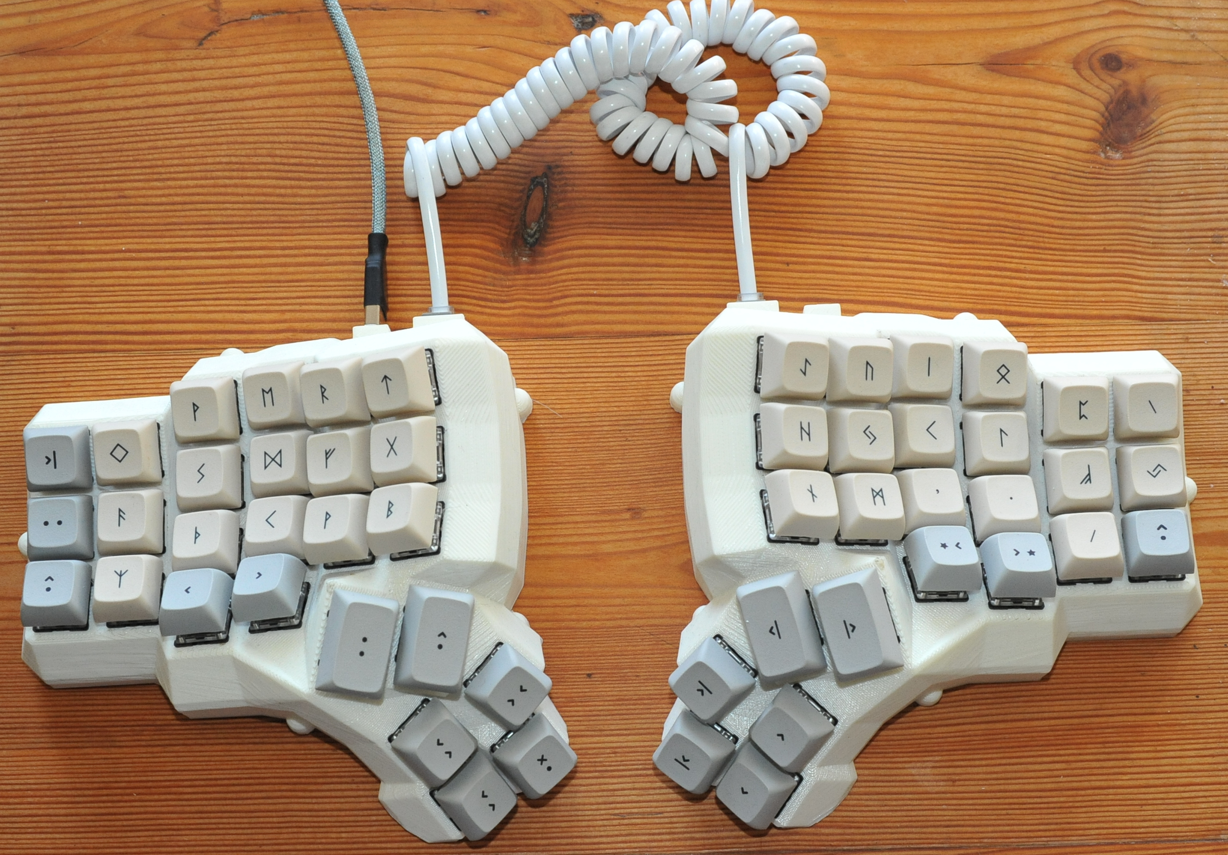
Figure 2: My 2018 Manuform build, from above (including hand made USB cable)
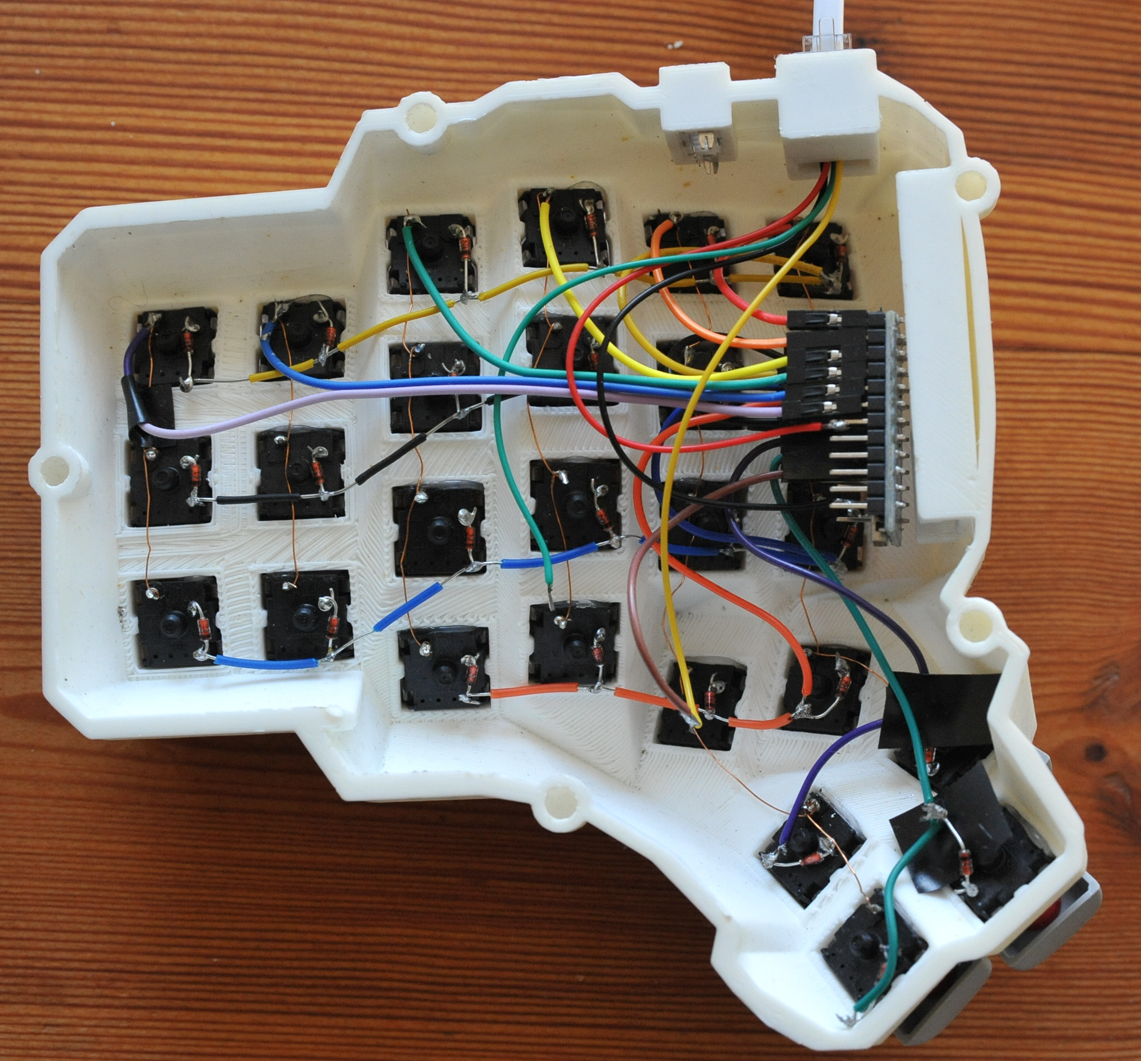
Figure 3: My 2018 Manuform build, from below
Moving to the Kinesis Advantage opened up a rabbit hole of infinite depth.
1.1. Material used
Material prerequisites for the build:
- 2 Microcontrollers (Arduino, or Teensy)
- 70 Key switches (e.g. something from Cherry MX, Gateron, etc)
- 70 Keycaps (that match mounting pin of the key switch)
- 70 Diodes (1N4148)
- Soldering, tin, wires,
- Access to 3D printer, (or send it off to 3D printing)
- Optional: Multimeter for testing continuity
2. 3D Modeling
2.1. Plan for modifying model
The model files are readily available pre-rendered in the Dactyl repo. However, there are a number of things I’d ideally like to change with the vanilla Dactyl:
- Cherry mount
- Change from Alps/Matias to Cherry MX compatible mount (current master on commit e0416e from 2017-06-25) is on Alps.
- TRRS jack replaced by RJ9
- This is because I have the latter but not the former for my build, which in turn is an effect of the wise crowd on the Internet report that TRRS jack is bad for digital signal, as it has a tendency glitch. I’ve seen other’s use GX12 connector. Any cable with 3 wires will do.
- Make interior of support pillars hollow
- The inner wall will add strength.
- Make leg attachment to case tapered
- This significantly decreases the likelihood for the legs to snap off.
- Add F-key row
- This would make it 1:1 with Kinesis Advantage layout.
- Outer columns are 1.25 u wide
- Since I have the keys, and this is the layout of the Kinesis. (Assuming I have Scandinavian umlaut keys (Å,Ä,Ö) of this size).
2.2. How to change the 3D model
There are several popular programs for 3D CAD modeling,
- Fusion 360
- Popular for Windows / OSX, and free (for individuals)
- FreeCAD
- Open source, available for GNU/Linux
- Blender
- Best for free hand sculpting
- onshape
- Cloud based, simple & powerful
For code -> 3D models there:
- OpenSCAD
- Most well established scripting 3D model
- PythonOpenSCAD
- Use Python + OpenSCAD
- build123d
- Pythonic, parametric, CAD
- CadQuery
- Python scripting
- ImplicitCAD
- “math inspired in Haskell” (abandoned?)
However, since the original model for this keyboard is defined in clojure (via OpenSCAD), a Lisp dialect, I’ll continue development using Emacs with CIDER-mode. (See braveclojure for introduction to Clojure + Emacs). I run it by
Install and run:
lein repl
- In Emacs, run M-x
cider-jack-in - To generate openscad output: M-x
cider-eval-bufferorcider-eval-region - open scad file for rendering (F6) and export to
*.stl.
3. 3D Printing
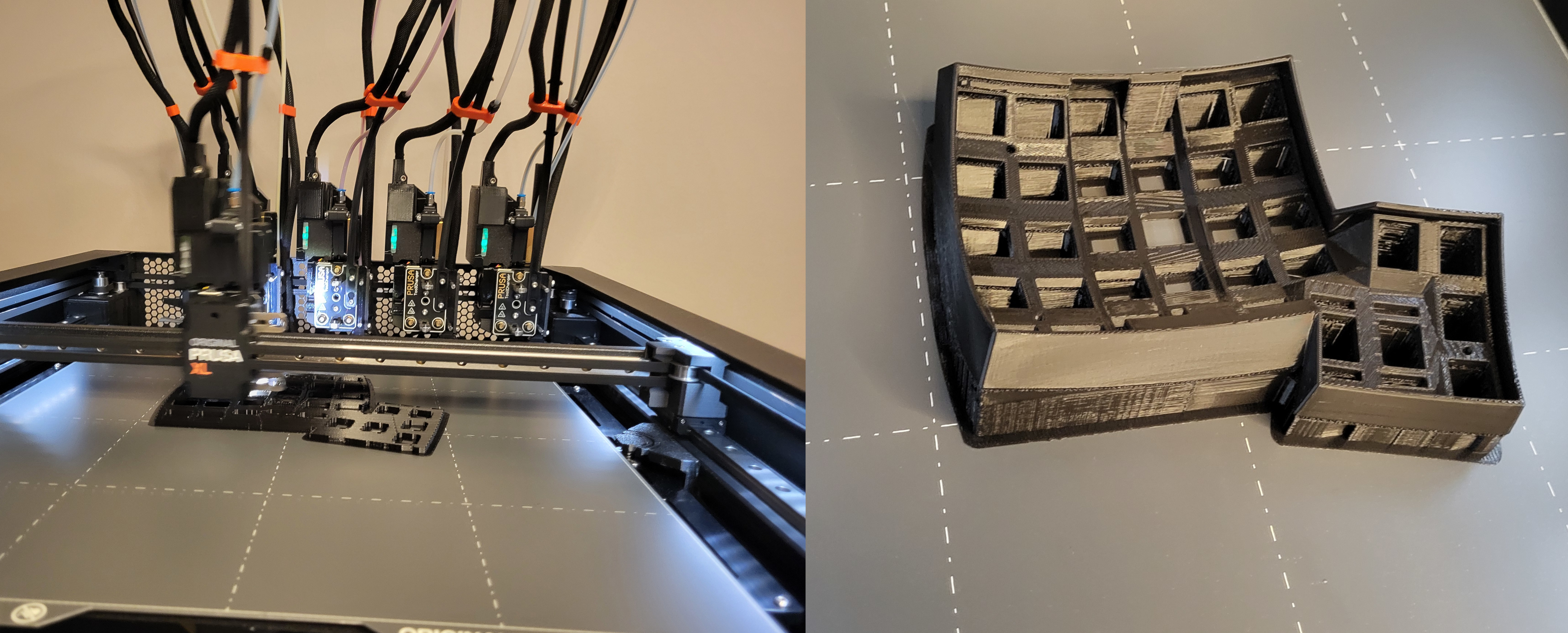
Figure 4: Printing the upper key switch mounting fixture, using 3D printer at work
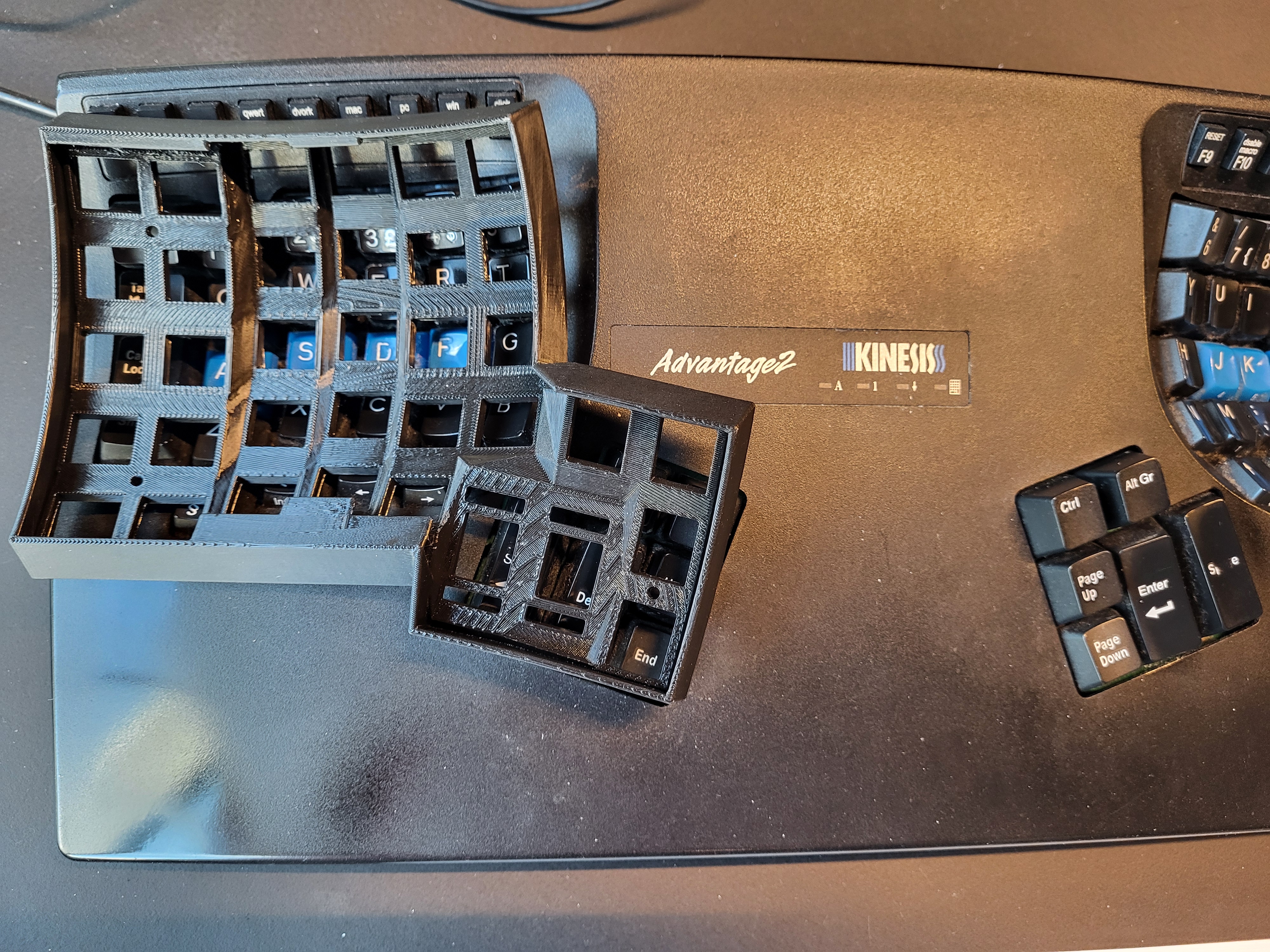
Figure 5: Best of both worlds: similar to my Kinesis Advantage keyboard, but split.
3.1. Where to print - Finding a 3D printer
There are multiple companies that offer 3D printing, like shapeways, or PCBWay, or just check your local advert market, and people with 3D printers offer to print for compensation. The Dactyl Manuform I printed in 2018, I printed for free in the local Makerspace. See if your city has one. (Also check your library).
In my case, my work decided to buy a 3D printer, with several kilos of filament, of PLA and PETG. I’m opting for the latter, as it is not sensitive to UV light, has higher heat tolerance (it’s very hot at the office during weekends when the climate system is turned off).
3.2. How to print - Slicer
To print a 3D model it must be processed in a slicer that knows specifications of the printer (e.g. model, nozzle size) and the filament to be used (e.g. PLA or PETG), and will output full trajectory in [\(x\), \(y\), \(z\)] for how the nozzle will move to create the model, in a G-code file.
There are several slicer programs, each supporting many printers, even cross manufacturer. They can differ in print speed, support material for floating parts, etc.:
- PrusaSlicer (what I’m using),
- Cura (What I used previously for my Dactyl Manuform build, on Ultimaker machines),
- Slic3r,
- Simplify 3D (proprietary, costs money)
3.3. How to configure slicer
The first print I printed standing on the build plate aligned the same way it will be used on my desk. It quickly broke in half as I was removing the build support structure, as the stress lines and print layers aligned (see figure 6 below).
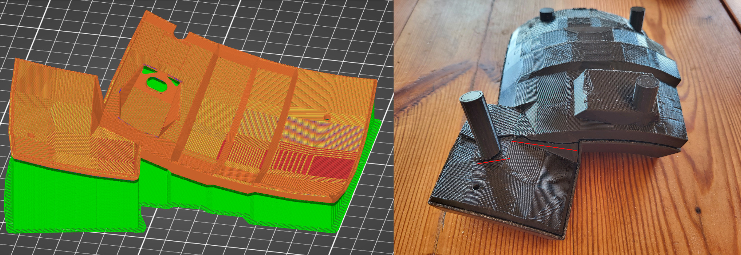
Figure 6: Bottom right part: Broke along the print layer (red lines) when removing support material (green)
Solution:
- Change from 2 to 3 perimeters under “Layer’s and perimiters” as suggested by Maker’s Muse video “5 Slicer defaults I ALWAYS change #3DP101”
- Rotate bottom on the build plate such that thumb cluster’s stress point along its attachment to the rest of the bottom board runs perpendicular to the print layers, as suggested in the very useful video “5 must-know 3D printing tips & tricks” on how to achieve stronger prints.
Thus I printed anew:

Figure 7: 90 degree rotated, makes it significantly stronger
4. Post processing
After the print is done, I sandpaper it with (in order) 120-, 240-, 400-, and 1200- grit sandpaper (my local hardware store did not have any 600, or 800) to smooth out the layering lines. (There are other methods, like applying epoxy resin like XCT-3D)
The surface becomes butter smooth, although you can still see the stripes from the additive printing process, and at times I’ve almost sanded through a layer.
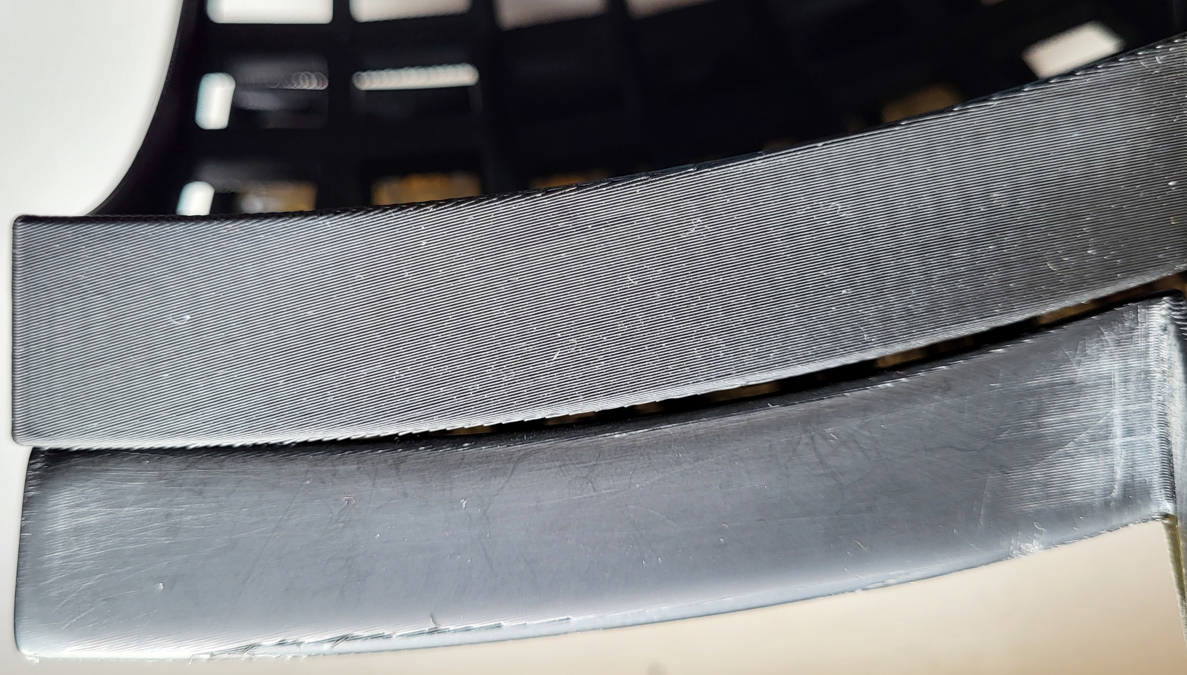
Figure 8: Comparison of raw print vs. post-prcessed with sandpaper.
Other post-processing steps to consider are [from prusaprinters]:
- “Large and thin surfaces can be reinforced with a polyester resin that improves the structural strength of the whole model. Add a hardener to the mixture according to the manufacturer’s instructions. It’s better to prepare smaller amounts that you will actually use up. Mix the resin in a bowl with a brush (keep in mind that the bowl and the paintbrush will be unusable after this procedure).”
- “Once the model has been roughly sanded, we can move to fill the gaps between single parts. I recommend using body filler used in the automotive industry. Apply a thin layer on the gaps and let it dry. Once the model has dried, polish it with P100 sandpaper. Keep repeating this procedure until the gaps are not visible. Once the model is ready, we can apply a layer of putty/body filler onto the rest of the model, and then sand it with a P100 sandpaper. And we basically repeat this step over and over (and over) until the model is beautifully smooth.”
5. Switches
The topic of switches is one of infinite deep rabbit hole. Most switches, keycaps and mounting plates are adapted for Cherry MX switches and their clones like Kailh, Gateron, Outemu, etc. (another is the more unusual Matias / Alps switches).
5.1. Types
The characteristic of a switch can be divided into tree main classes:
- Linear
- Same force all the way
- Tactile
- Force increase into a tactile “bump” when switch is activated
- Clicky
- Same as tactile, but also has a click-leaf or spring
- Cherry MX blue
- Kailh blue
- Kailh box white (or jade, or navy)
- Novelkeys sherbet
5.2. Deeper into the rabbit hole
Then comes a slew of different factors that affect the switch, such as:
- Plastic type
- e.g. some plastics are self lubricating, POM (Polyoxymethylene) is a popular one among the keyswitch aficionados
- Springs
- force, material
- Force profiles
- the force vs. distance traveled/pressed
- Sound
- many different mechanisms for “click” or to silence
- Lubrication
- yes / no, which type
- Dampening rings
- one or several rubber rings around the keycap mounting stem
- Manufacturer & model
- a real smörgårdsbord, e.g. some on my radar
- Kailh silent brown (45gF, popular, silent, noticeable tactile bump)
- cherry MX brown (55gF): scratchy almost linear
- cherry MX blue (60gF)
- Lekker Switch
- Cherry MX mounted Model M / buckling spring switches
Recently, there are also contactless HAL effect switches, as in the 1970s, that use magnetic flux to register the key event. At the time of writing I do not believe these can be used in hand wired keyboards.
5.3. Modify switches for pinky finger
The key switches have a spring force of 45 gF. Since I only use my weak pinky finger for the outer column keys, I swap them for lighter 35 gF loaded springs. I have a 3D printed Cherry MX switch opener (orange in the picture below) that speeds up the process.
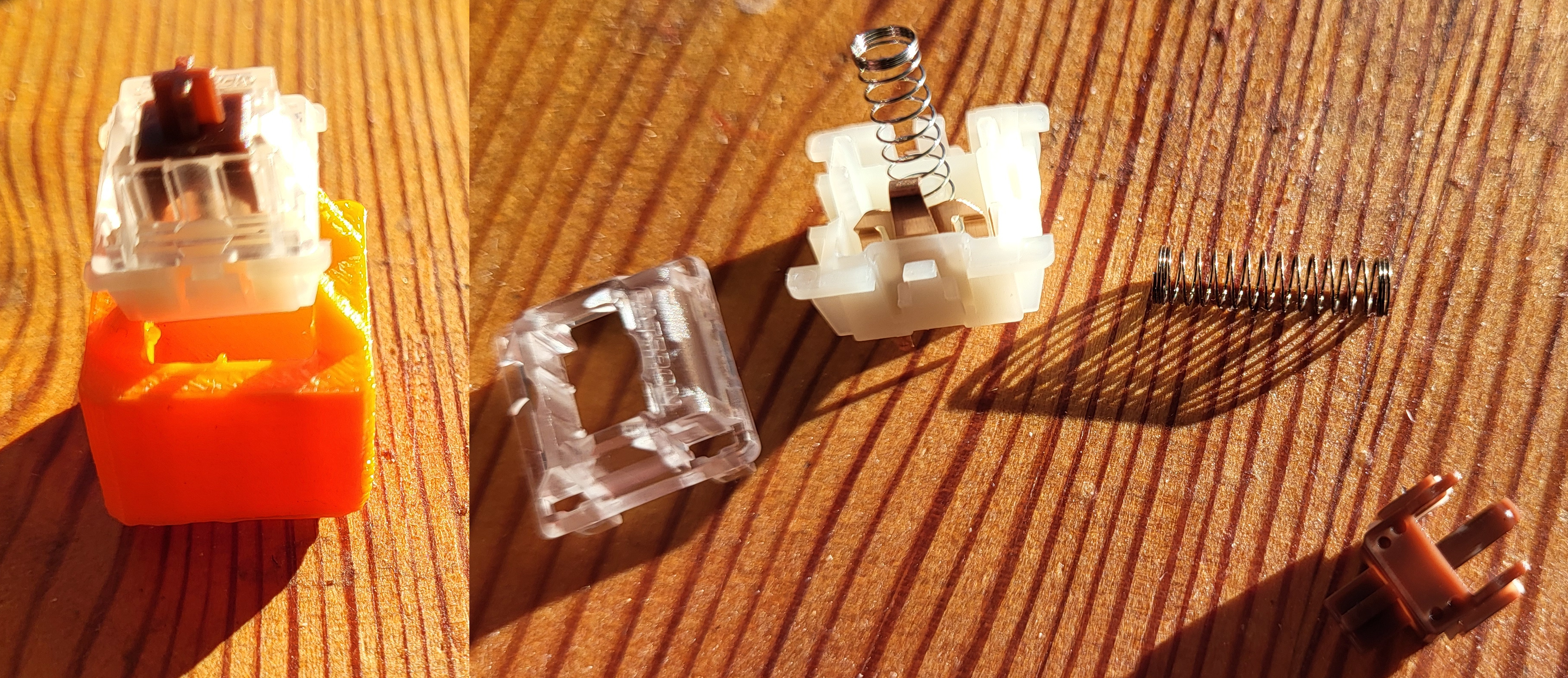
Figure 9: Opening a switch and replacing 45 gF spring with 35 gF
5.4. Hot swappable switch and diode mounts
Soldering all the switches and diodes in place is a menial task. What’s worse is, if I want to change to a different switch in the future (e.g. a linear or clicky switch) I would have to de-solder everything, then repeat the process again.
- Solution 1
- There are hotswap sockets, e.g. from kailh (although intended for PCB). As demonstrated by a user on reddit, you can use these with a Dactyl (Manuform) build (gallery). Note: these do not include the diode.
- Solution 2
I found a 3D model on thingiverse for mounting diode + switch into a matrix using steel wires (24 gauge, corresponding to 0.55 mm) that fit my needs perfectly. I did make slight changes to the source on github:
- added comments
- made accommodations of 0.65 mm steel wire, rather than the 0.55,
- flipped it 180 degrees as it would have printed with top side down, as indicated by the author’s comment
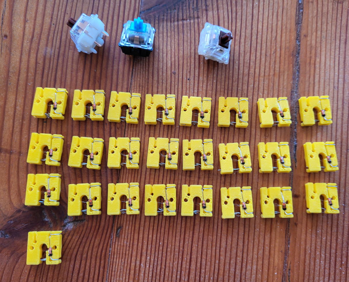
Figure 10: Hotswap mounts with diodes
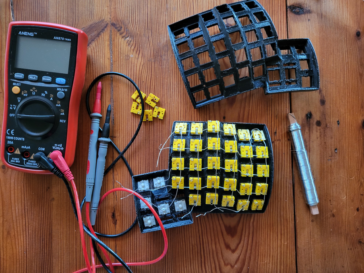
Figure 11: Assembling hotswap mounts
During the pairing of switch to mount plate, I found the multimeter to be indispensable:
- Use continuity mode on multimeter to check the hotswap mount has connected properly with the switch, such that no leg is bent, rather than going through the hole of the yellow plate.
- Use diode setting on multimeter to check the matrix once columns and switches were fully connected to a matrix, and test all 35 x 2 switch.
5.5. Dampening with rubber o-rings
On my original Dactyl Manuform print, I opted to put double rubber (silicone) O-rings on the stem of each switch for dampening. They come in different thickness, and hardness (e.g. as measured by the Shore Durometer scale).
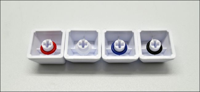
Figure 12: Example of O-rings (not by me, source)
5.6. Addendum: The “Void Switch”
Interestingly, there’s now a completely new switch, hacked together by 3D printing and using just magnets (3 magnets for each switch), named “Void Switch”. However, it is not MX compatible, but requires a special PCB for mounting.
Chyrosran22 has a video Teardown - 3D-printed magnetic levitation “Void” switches! of the switch, and the creator has a youtube channel (and a new one). This seems very promising, and one should be able to combine it with this Dactyl model (potential future project).
6. Wiring it up
In order to make the keyboard work, we need to wire each switch to the microcontroller(s), and define the physical keyboard layout in firmware and flash it to the microcontroller. For this we use QMK which is incredibly versatile (e.g. see QMK-tutorials here).
6.1. Hardware: The Microcrontroller
Arduino Pro Micro controller pin out (from Arduino pin out) needed to wire up the columns and rows and match in source (for more, see sparkfun, and geekhack forum post). Since we’re using split configuration, both micro controllers must be of same type.
SERIAL ARDUINO  PORTS PIN     PIN  PORTS  ARDUINO SERIAL
                         +---+
                     +---|USB|---+
 TX1     D1      PD3 |TXO|   |RAW| RAW (+5V from USB)
 RX1     D0      PD2 |RXI+---+GND| GND
                 GND |GND =*= RST| Reset
                 GND |GND =!= VCC| Vcc (+3V*)
 SDA     D2      PD1 |2    X   A3| PF4     A3      TCK
 SCL     D3      PD0 |3   / \  A2| PF5     A2      TMS
      A6/D4      PD4 |4  X   X A1| PF6     A1      TDO
         D5      PC6 |5   \ /  A0| PF7     A0      TD1
      A7/D6      PD7 |6    X   15| PB1     D15     SCLK
         D7      PE6 |7  +---+ 14| PB3     D14     MISO
      A8/D8      PB4 |8  |   | 16| PB2     D16     MOSI
      A9/D9      PB5 |9  +---+ 10| PB6     D10     A10
                     +-----------+
                    (On board LEDS):
 SS      D17     PB0  RXled TXled  PD5     D30
Since we wire the halves together by connecting VCC<->VCC and GND<->GND
and 3<->3 serial communication happens on pin 3, i.e. PD0 (but could use
any of PD0/PD1/PD2/PD3 ), which we specify in config.h
6.2. Wetware: Planned layout of keys
Below is the planned layout that I have in mind, (using keyboard-layout-editor, there is also Ergogen for ergonomic keyboards, that given a 2D specification generates files for build plate and PCB).
The layout mimics the layout of the Kinesis Advantage that I’ve been using daily for +10 years, minus function key row plus an additional keys in the bottom outer corner of each half.
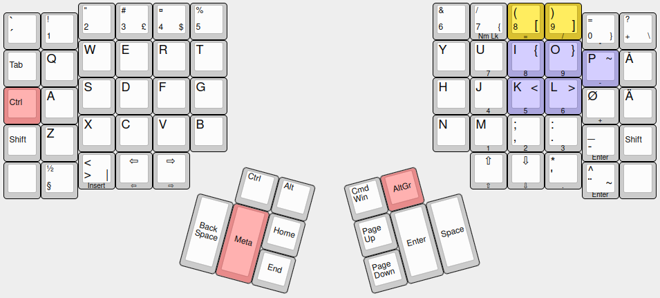
Figure 13: Key layout (config in appendix) differs from Kinesis by +2 more keys (bottom corners), and no F-keys.
6.3. Wiring: Layout in practice
Below, each column and each row is connected, and connected to one of the pins of the microcontroller. (todo: 3 more wires are needed for the 3.5 mm jack that will connect the halves).

Figure 14: Wiring of one half of the keyboard
Mapping figure 14 to the way I’ve connected each switch to a row and column position, we’ll get the key matrix below:
NOTE: the right hand side is mirrored, so either use different
MATRIX_COL_PINS when compiling firmware for either side, or mirror PIN
diagram as well, see column Pins (cPIN) below:
Pin out for rows and columns (cPIN and rPIN), and corresponding port in source (SRC) code:

SRC:   PD1 PD4 PC6 PD7 PE6 PB4 PB5                  SRC:   PB5 PB4 PE6 PD7 PC6 PD4 PD1

cPIN:   2   4   5   6   7   8   9                   cPIN:   9   8   7   6   5   4   2

rPIN:   |   |   |   |   |   |   |     SRC:          rPIN:   |   |   |   |   |   |   |    SRC:
  A2  --'---1---2---3---4---5--lALT-- PF5             A2 -rCTR--6---7---8---9---0---+--- PF5
        |   |   |   |   |   |   |                           |   |   |   |   |   |   |
  14  -TAB--Q---W---E---R---T--END--- PB3             14 -PGDN--Y---U---I---O---P---Å--- PB3
        |   |   |   |   |   |   |                           |   |   |   |   |   |   |
  A1  -CTR--A---S---D---F---G--WIN--- PF6             A1 -rALT--H---J---K---L---Ö---Ä--- PF6
        |   |   |   |   |   |   |                           |   |   |   |   |   |   |
  15  -SHF--Z---X---C---V---B--HOME-- PB1             15 -PGUP--N---M---,---.---_--rSHF- PB1
        |   |   |   |   |   |   |                           |   |   |   |   |   |   |
  A0  -   --½--INS-LFT-RGT-BKSP-META- PF7             A0  -RET-SPC--UP-DWN--*---^--   -- PF7

  Serial connection between the halves:
                               SRC:   PIN:            PIN:   SRC:
                               Vcc    VCC <---------> VCC    Vcc
                               GND    GND <---------> GND    GND
                                3     PD0 <---------> PD0     3
Technically, the QMK firmware considers this one board, with right half
beneath the left, thus if each half has \(N\) rows, the firmware considers
this to be a board with \(2N\) rows, with lefft stacked on top of the right
half (notation K<row><column>):
Pin out for rows and columns (cPIN and rPIN), and corresponding port in source (SRC) code:

SRC:   PD1 PD4 PC6 PD7 PE6 PB4 PB5                  SRC:   PB5 PB4 PE6 PD7 PC6 PD4 PD1

cPIN:   2   4   5   6   7   8   9                   cPIN:   9   8   7   6   5   4   2

rPIN:   |   |   |   |   |   |   |     SRC:          rPIN:   |   |   |   |   |   |   |    SRC:
  A2  -K00-K01-K02-K03-K04-K05 K06- PF5             A2    -K50-K51-K52-K53-K54-K55-K56- PF5
        |   |   |   |   |   |   |                           |   |   |   |   |   |   |
  14  -K10-K11-K12-K13-K14-K15-K16- PB3             14    -K60-K61-K62-K63-K64-K65-K66- PB3
        |   |   |   |   |   |   |                           |   |   |   |   |   |   |
  A1  -K20-K21-K22-K23-K24-K25-K26- PF6             A1    -K70-K71-K72-K73-K74-K75-K76- PF6
        |   |   |   |   |   |   |                           |   |   |   |   |   |   |
  15  -K30-K31-K32-K33-K34-K35-K36- PB1             15    -K80-K81-K82-K83-K84-K85-K86- PB1
        |   |   |   |   |   |   |                           |   |   |   |   |   |   |
  A0  -K40-K41-K42-K43-K44-K45-K46- PF7             A0    -K90-K91-K92-K93-K94-K95-K96- PF7

  Serial connection between the halves:
                               SRC:   PIN:            PIN:   SRC:
                               Vcc    VCC <---------> VCC    Vcc
                               GND    GND <---------> GND    GND
                                3     PD0 <---------> PD0     3
7. TODO Firmware
7.1. DONE Set up
Last time I set up QMK, you git cloned the repository and then edit the
source directly, and then ran make, i.e. the usual way on Linux.
However, things are more “smooth” now, as it is installed as a python
package, either through your package manager, or directly through pip:
pip install qmk
run (answer ’y’ to most prompts):
qmk setup
or specify home folder:
qmk setup -H <path>
qmk setup --help
test building a default keymap
qmk compile -kb <keyboard> -km default
qmk compile -kb clueboard/66/rev3 -km default
7.2. TODO Edit
Define a new keyboard:
qmk new-keyboard -kb dactyl2024
In the list of pre-defined keyboards, choose none of the listed, and move directly to choose which compatible micro controller you have (for me:
atmega32u4), which results in a folder:keyboards/dactyl2024being created, relative qmk source root folder.Create a keyboard map (using default keyboard above):
qmk new-keymap
if no default keyboard set:
qmk new-keymap -kb <keyboard-name>
resulting in a
keymap.cfile inkeyboards/dactyl2024/keymaps/impaktorThe QMK documentation describes how to build the firmware. They suggest to first define your default keyboard (e.g.
clueboard/66/rev4, or in my casedactyl2024):qmk config user.keyboard=dactyl2024
and set keyboard map (usually named after your github nick):
qmk config user.keymap=impaktor
- TODO Edit files that define the configuration:
- info.json, QMK now supports this file to be the “Single Source of Truth”, i.e. from this file we can generate config.h and rules.mk.
- QUESTION: is config.h and rules.mk generated from info.json?
- config.h, defined keycodes (also see keycodes FAQ)
- For non-US layouts, you can reduce confusion in the code by using umlaut etc. labels, that are then internally mapped to US ANSI, which is interpreted by your OS to correct character. See Language-specific Keycodes
rules.mk, need to have:
SPLIT_KEYBOARD = yes
- QUESTION: where’s rules.mk? Is it generated? same folder as keymap.c and conifg.h
- config.h, defined keycodes (also see keycodes FAQ)
When changes have been made, compile:
qmk compile
or without default:
qmk compile -kb <keyboard> -km <keymap>
next, you should flash the firmware onto the board.
TODO:
- How does it know it’s split? Do I refine full mapping, or only one half, and the other mirrors it? https://docs.qmk.fm/features/split_keyboard
- if stuck, check discord for help: https://discord.gg/qmk
Quote from https://docs.qmk.fm/features/split_keyboard
However, since one of the wires carries VCC, this means that the boards are not hot pluggable. You should always disconnect the board from USB before unplugging and plugging in TRRS cables, or you can short the controller, or worse.
- Umlaut / additional key support: https://docs.qmk.fm/features/unicode#additional-language-support https://github.com/qmk/qmk_firmware/blob/master/docs/reference_keymap_extras.md
- Keycodes https://docs.qmk.fm/keycodes_basic https://docs.qmk.fm/quantum_keycodes
- NOTE: “You should always disconnect the board from USB before unplugging and plugging in TRRS cables, or you can short the controller, or worse.”
“cant connect…”? then add to dialout group:
sudo usermod -a -G dialout $USER, then log out and log back in.
7.3. Amazing features of a free firmware keyboard
Here are some of the special features of the keyboard.
7.4. my code
- consider disabling OLED https://docs.qmk.fm/squeezing_avr#oled-tweaks (once I’ve confirmed my setup works)
- make sure I’ve disabled RGB lighting https://docs.qmk.fm/squeezing_avr#rgb-settings
- specify left / right side:
- a pin is permanently high/low on one of them
- flash each EEPROM with left/right using bootloader parameter:
avrdude-split-left=/=avrdude-split-right - if usb-cable is always connected to right (flash both sides with
config.h):
#define MASTER_RIGHT
- Question: do I not need to set which pin serial communication happens on? Test first without it.
- I don’t think I need this for halves to detect:
#define
     SPLIT_USB_DETECT
“Teensy boards lack VBUS detection out of the box and must haveSPLIT_USB_DETECTdefined.” - TODO: read (but RGB part is outdated): https://github.com/nicinabox/lets-split-guide
Add to config.h (to reduce size, matters since very little space on the microcontroller):
#define NO_MUSIC_MODE           /* Disable music */
#define LAYER_STATE_8BIT        /* Max 8 layers */

/* not customizing magic keycodes */
#ifndef MAGIC_ENABLE
uint8_t mod_config(uint8_t mod) {
    return mod;
}
#endif

/* not using magic keycodes to swap modifiers */
#ifndef MAGIC_ENABLE
uint16_t keycode_config(uint16_t keycode) {
    return keycode;
}
#endif

/* Disable OLED */
/* Note: check if below old code is in the config.h and should be removed:

    // OLD CODE
    char wpm_str[4] = {0};
    sprintf(wpm_str, "WPM: %03d", get_current_wpm());
    oled_write(wpm_str, ' '), false);

 */
oled_write_P(PSTR("WPM: "), false);
oled_write(get_u8_str(get_current_wpm(), '0'), false);
rules.mk
MUSIC_ENABLE = no
SPLIT_KEYBOARD = yes
7.5. Flashing
Connect RST and GND to enter bootloader. If you’re using an official Sparkfun Pro Micro (the red one) you need to short this twice quickly.
You will have 8 seconds to flash before it continues on to the sketch.
> Tip: If this is the first time the Pro Micro has been flashed it should go directly to the bootloader on start. https://github.com/nicinabox/lets-split-guide/blob/master/flashing.md
8. Keycaps
Keycaps need to have pins compatible with the stem of the switch, e.g. Cherry MX or Matias/Alps stem. Cherry MX compatible is the most common and what I use.
I’ve long had a keycaps set from the Symbolics lisp machine reproduction group buy announced on geekhack made in the classic SA profile by Signature Plastics (GMK and Signature Plastics are generally considered the best manufacturers of keycaps, although new initiatives are made for new profiles like MT3). It is still available at kono.store by the looks of it. This is the most expensive part of the keyboard, as demand is high, and a lot of work goes into making it. An alternative solution I’ve considered would be to buy a blank Kinesis Advantage keycap set ($50, or 720 NOK).
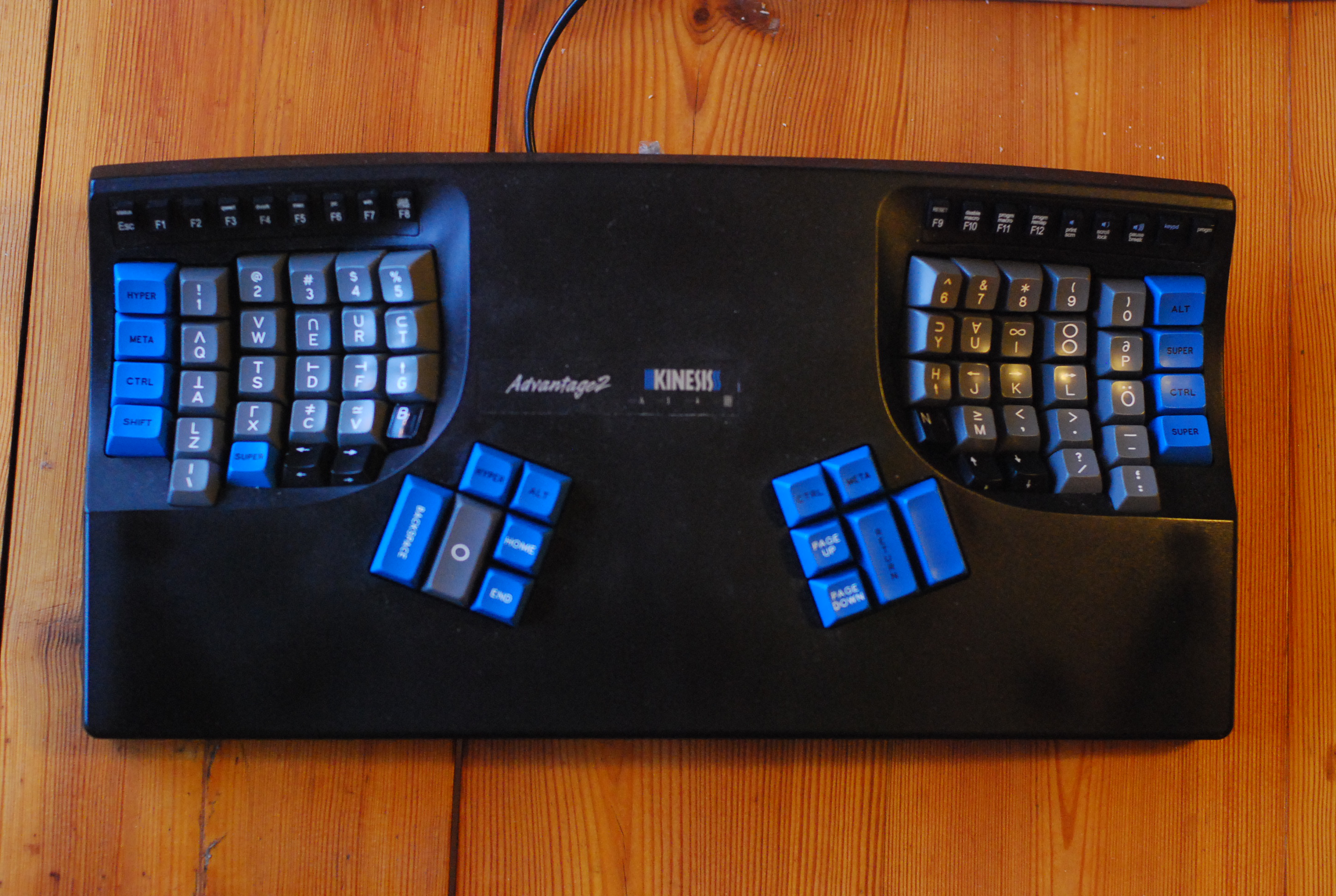
Figure 15: My beloved Kinesis Advantage 2, here with the Symbolics SA uniform keycaps. Note the outer column’s u1.25 wide keys
(For an entertaining review of the original Symbolics “Space Cadet” Honeywell Hall effect keyboard: Chyrosran22)
9. End - Finished result
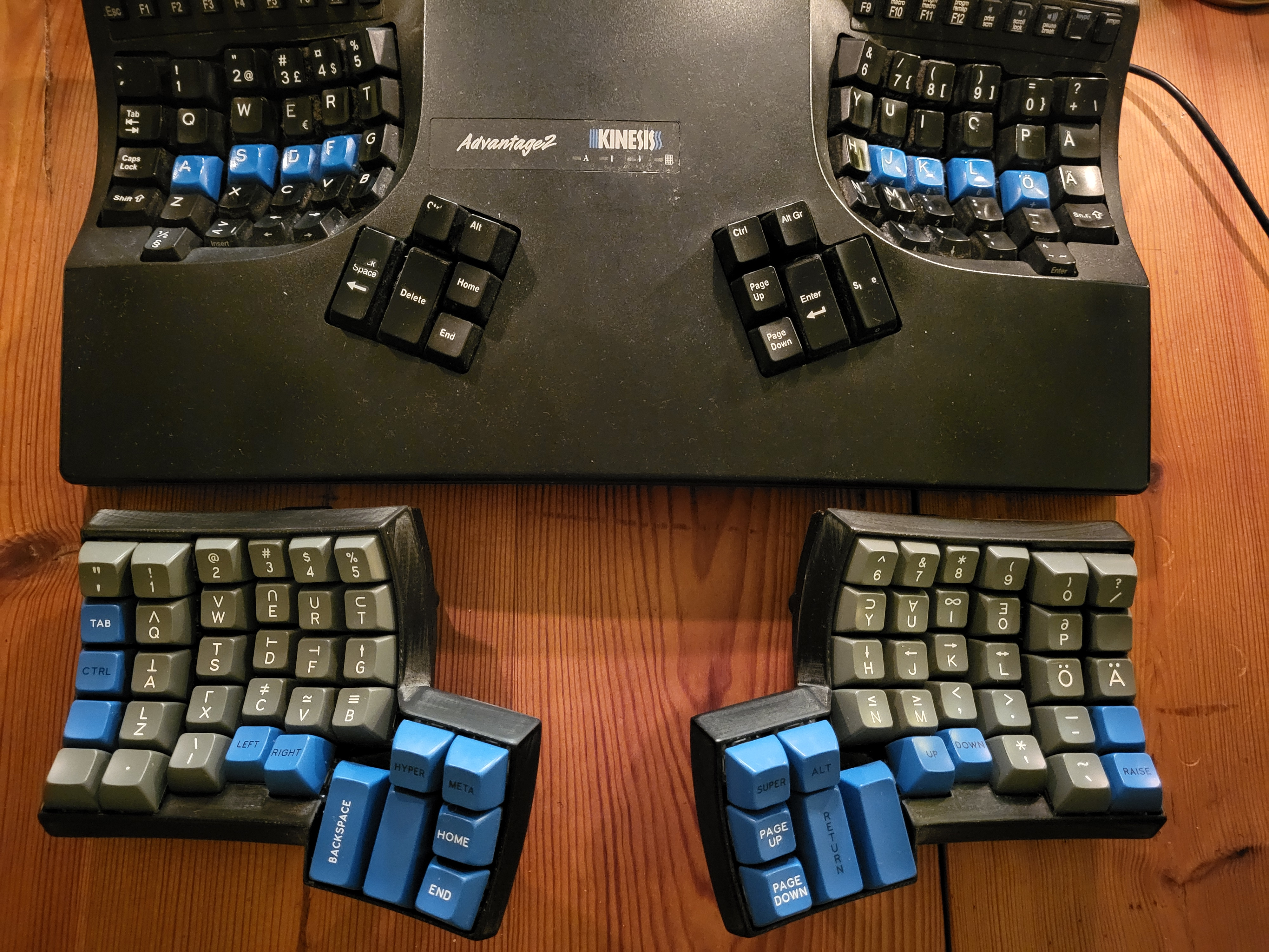
Figure 16: My trusty Kinesis with the (almost) finished Dactyl, same keyboard layout
10. Appendix
- Adding extra keys to your Kinesis Advantage
- Design PCB and case from scratch?
- KiCAD PCB keyboard design plugin, makes stuff a lot simpler: kicad-kbplacer
- Hand wiring A complete guide to building a hand wired keyboard
10.1. Parts / store
10.2. Keyboard layout raw
Layout for figure 13 above.
[{x:2.25},"\"\n2","#\n3\n\n£","¤\n4\n\n$","%\n5",{x:5.5},"&\n6","/\n7\n\n{\nNm Lk",{c:"#d9c030",fa:[6,0,0,6]},"(\n8\n\n[\n=",")\n9\n\n]\n/"],
[{y:-0.75,x:0.25,c:"#cccccc",f:6},"`\n´",{f:3},"!\n1",{x:13.5},"=\n0\n\n}\n*","?\n+\n\n\\"],
[{y:-0.25,x:2.25,f:6},"W","E","R","T",{x:5.5},"Y","U\n\n\n\n7",{c:"#aba6de"},"I\n\n{\n\n8","O\n\n}\n\n9"],
[{y:-0.75,x:0.25,c:"#cccccc",a:6,f:3},"Tab",{a:4,f:6},"Q",{x:13.5,c:"#aba6de"},"P\n\n~\n\n-",{c:"#cccccc"},"Å"],
[{y:-0.25,x:2.25},"S","D","F","G",{x:5.5},"H","J\n\n\n\n4",{c:"#aba6de"},"K\n\n<\n\n5","L\n\n>\n\n6"],
[{y:-0.75,x:0.25,c:"#e88b8b",a:6,f:3},"Ctrl",{c:"#cccccc",a:4,f:6},"A",{x:13.5},"Ø\n\n\n\n+","Ä"],
[{y:-0.25,x:2.25},"X","C","V","B",{x:5.5},"N","M\n\n\n\n1",";\n,\n\n\n2",":\n.\n\n\n3"],
[{y:-0.75,x:0.25,a:6,f:3},"Shift",{a:4,f:6},"Z",{x:13.5},"_\n-\n\n\nEnter",{a:6,f:3},"Shift"],
[{y:-0.25,x:2.25,a:4,f:6},"<\n>\n\n|\nInsert",{a:5,f:5},"⇦\n\n\n\n⇦","⇨\n\n\n\n⇨",{x:7.5},"⇧\n\n\n\n⇧","⇩\n\n\n\n⇩",{a:4,f:6},"*\n'\n\n\n."],
[{y:-0.75,x:0.25,a:7,f:3},"",{a:4},"½\n§",{x:13.5,f:6},"^\n¨\n\n~\nEnter",{a:7,f:3},""],
[{r:15,rx:5.25,ry:4,x:1.5,a:4},"Ctrl","Alt"],
[{x:0.5,a:7,h:2},"Back<br>Space",{c:"#e88b8b",h:2},"Meta",{c:"#cccccc"},"Home"],
[{x:2.5},"End"],
[{r:-15,rx:12.75,x:-3.5,a:4},"Cmd\n\n\n\n\n\nWin",{c:"#e88b8b",a:7},"AltGr"],
[{x:-3.5,c:"#cccccc",a:6},"Page<br>Up",{a:7,h:2},"Enter",{h:2},"Space"],
[{x:-3.5,a:6},"Page<br>Down"]
